Viewer Guide
Overview
This document guides you through the basic camera setup with Vimba X Viewer. You will learn how to select, control, and save settings such as image size, exposure time, and color display.
For Allied Vision GigE and USB cameras, the Bandwidth Manager tool is available.
See also
For information on camera and driver installation and a detailed feature description, download the corresponding documents for your camera.
Note
Depending on the camera model, different features are available. The screenshots and examples in this document are generic.
Prerequisites
This manual assumes you have already installed and configured the host adapter card or frame grabber according to the instructions for your camera.
Quick start
You can access Vimba X Viewer from the Windows Start menu or in the Vimba X install directory /bin.
To use the Viewer:
Connect the camera to the host.
Start Vimba X Viewer.
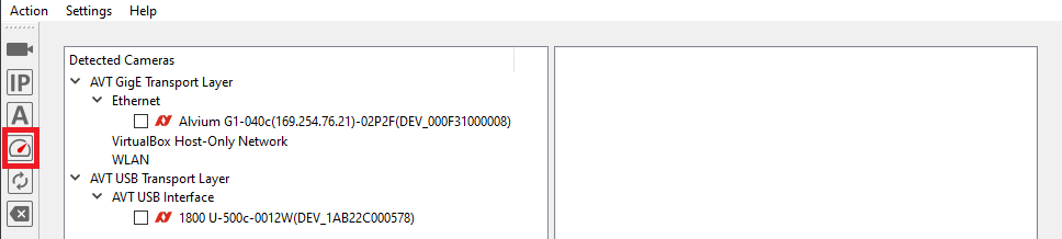
Make sure to select the AVT transport layers on top of the list.
Click the camera you want to open.
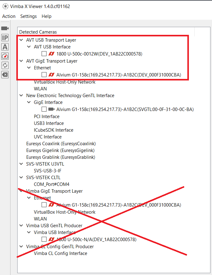
Select the AVT TLs and open a camera
The main window opens.
To start image acquisition, click Freerun.
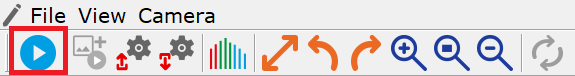
Start continuous image acquisition (freerun)
Camera not detected
USB camera
Unplug the camera and plug in the camera again.
Windows only: Check with the Vimba X Driver Installer if the driver is installed.
GigE camera
If the camera is connected to a switch, make sure that the switch is in the same subnet as the camera.
If the problem persists, Vimba X Viewer offers several possibilities:
Open camera by…
Click Open camera…, which opens the camera if you type in the IP address, Camera ID, or MAC address. Each Alvium camera has its MAC address printed on the housing. It looks like this: 000A47000CA2.
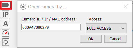
Open camera by…
Configure IP:
Click ConfigureIP. The screenshot shows a configuration example.
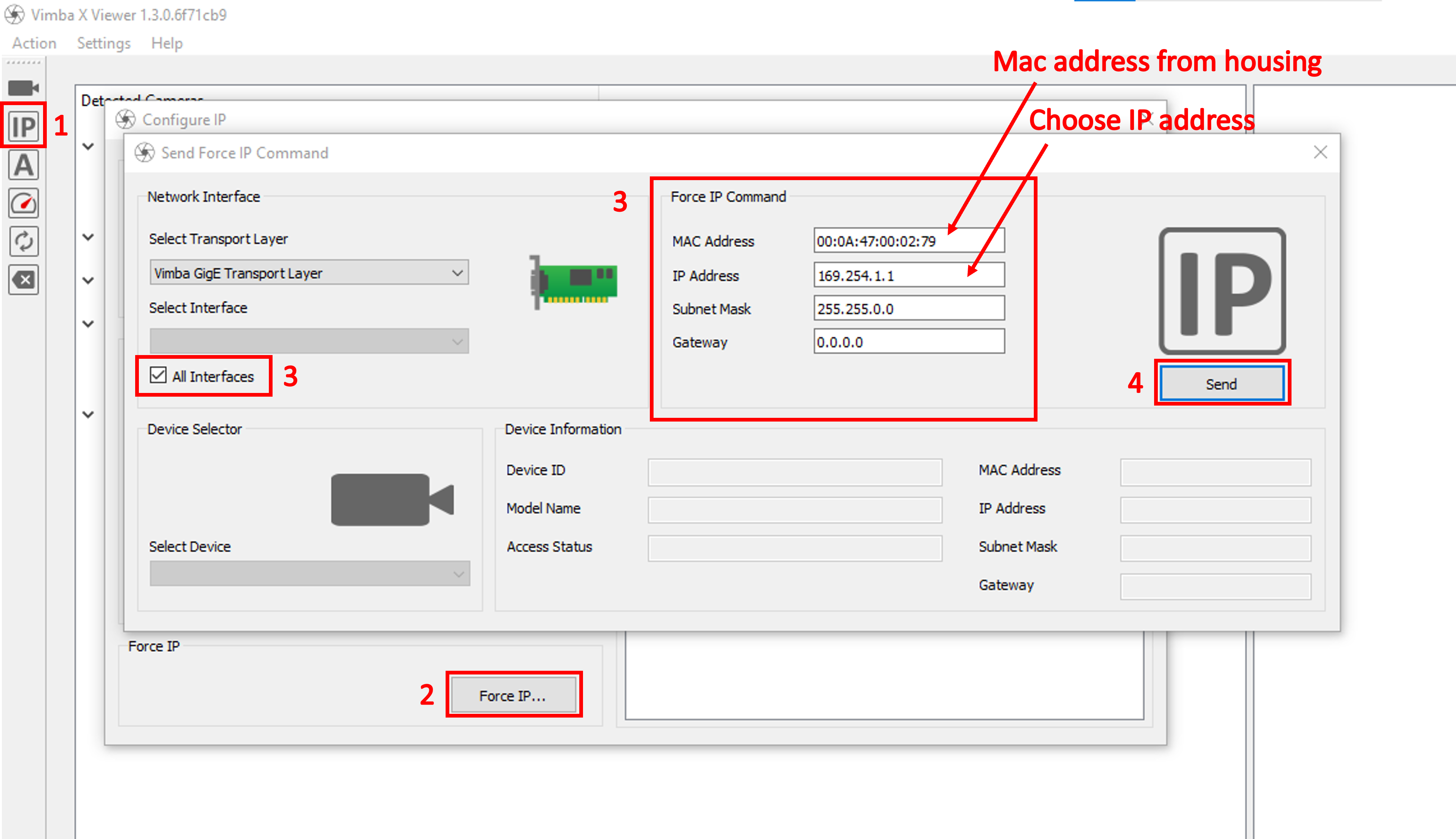
Force IP configuration example
Note
The Configure IP dialog doesn’t update the camera list.
See also
For smooth operation and best performance of your GigE camera, follow the instructions for your camera.
CSI camera:
Before using Vimba X, install the driver. It is provided at https://github.com/alliedvision.
CSI-2 is not a plug and play interface. To update the camera list, reboot the board.
Viewer tabs concept
To select and configure settings, Vimba X Viewer provides tabs with basic grouped camera features and the All tab, which contains a list of both the basic features and advanced features.

Viewer tabs
To quickly set up your camera, we recommend going through the tabs from left to right. The basic features can be adjusted either on the All tab or on the other tabs, whereas advanced features are available on the All tab only.
Note
The Color tab is available for color cameras only.
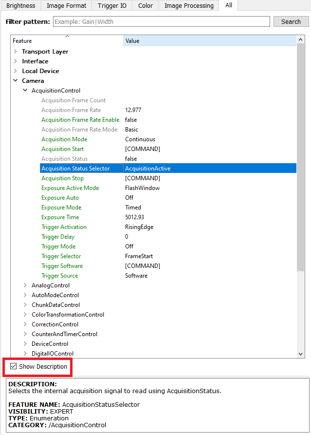
Finding features in the All tab
To quickly find features from the other tabs in the All tab, enter their first letters in the Search field.
The All tab provides tooltips and an optional feature description window. The description also lists which other features are affected by the selected feature.
Tooltips
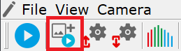
Starting and stopping image acquisition
To start and stop image acquisition, click Freerun.
Freerun
Loading and saving settings
Additionally to the user sets stored inside the camera, you can save the feature values as an XML file to your host PC. You can load this camera settings XML file to a camera or use the XML file with the Vimba X APIs. To load or save a settings file, click Load and Save.
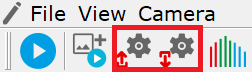
Load and save settings
Using saved settings files with Vimba X API
To use a saved settings file with Vimba X API:
Set up your camera with Vimba X Viewer.
Save the settings.
Load the settings with the API (see the example and the API manuals).
Saving images
Saving one image
In the File menu, click Save Image As…
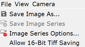
File menu
The Save Image window opens and you can save one image.
You can save the current image while the camera is running or you can save the current image displayed in Vimba X Viewer while the camera is stopped.
Saving an image series
If the camera is running, stop image acquisition.
In the File menu shown above, click Image Series Options….
The Saving Options window opens. In the dialog, make sure the Number Of Images is > 0, select the other options, and click OK.
Now Save Image Series is active. Clicking it triggers acquiring and saving the defined number of images. You can also use the icon:
Save image series
If the icon is grayed out, make sure that image acquisition is stopped and the selected number of images is > 0.
Saving 16-bit images
By default, Vimba X Viewer saves 8-bit images, regardless of the selected pixel format or file format. Optionally, all images with mono or Bayer pixel formats > 8-bit per channel (e.g., Mono10, BayerRG12Packed, Mono14) can be saved as 16-bit TIFF. To enable this option, select Allow 16-Bit TIFF Saving.
Save 16-Bit Tiff
Tip
The option for saving 16-bit image files is not optimized for performance. Therefore, it is deselected by default when a camera is opened. We recommend selecting it on demand.
16-bit image files are saved if these conditions are true:
Allow 16-Bit TIFF Saving is checked.
TIFF or TIF is the selected file format for image (series) saving.
The camera’s current pixel format is a mono or Bayer format > 8 bits per channel.
Options
Go to View → Options to:
Display every completed frame (increases CPU load, not recommended for most use cases)
Change the number of used frame buffers
Enable or disable Alloc and Announce, which may optimize buffer allocation (depending on your use case).
Bandwidth Manager
Purpose and scope
The Bandwidth Manager is available for Allied Vision GigE and USB cameras and their transport layers provided with Vimba X.
It is intended mainly for multi-camera applications, but you can also use it for a single camera. You can use the Bandwidth Manager as a starting point for best possible bandwidth allocation. The exact values for your use case depend on the camera settings, whether or not an image is displayed, and of course your hardware.
First steps
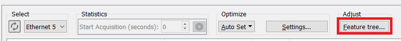
The Bandwidth Manager is accessible from the Viewer main window:
Open Bandwidth Manager
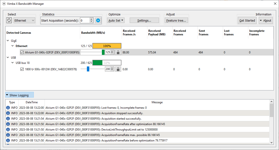
Bandwidth Manager
Tip
Use the tooltips to get quick information about the functionality.
First, select the interface whose bandwidth you want to manage:
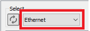
Select the interface
Tip
You cannot select multiple interfaces, each interface requires a separate bandwidth management.
Start image acquisition to obtain statistics. Optionally, enter enter a value for the duration of the image acquisition. If you entered a value, a countdown is shown.
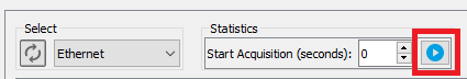
Start acquiring images and statistics
With the slider or by entering a value, you can change the bandwidth of each selected and unlocked camera manually and observe in the statistics if frames got lost or are incomplete.
Alvium and Goldeye cameras: DeviceLinkThroughputLimit determines the camera bandwidth.
Other Allied Vision cameras: StreamBytesPerSecond determines the camera bandwidth.
Note that for a consistent appearance each slider has the same length, but each camera may have different min and max values. The lowest possible value of a slider represents the lowest possible value of its camera and not zero:
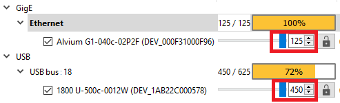
Slider - min and max camera value
Please also note that the displayed values are rounded.
To exclude a camera from the statistics collection, uncheck it.
Note
Changing the throughput limit may affect sensor timings like line time, jitter, and exposure start delay. Please consider this if your use case has special timing requirements.
Note that the displayed maximal value of the interface represents the value reported by the system, not the available bandwidth for camera images.
The value of the interface bandwidth cannot exceed 100%. Therefore, 100% can be displayed either yellow or red. The color representing the interface bandwidth also depends on the safety margins in the Auto Set settings (see next section below). Green or yellow color indicates that the interface bandwidth is within the safety margins.
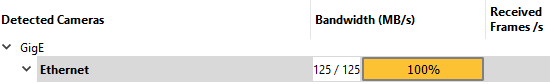
Interface bandwidth - max 100%
Automatic bandwidth optimization
Click Auto Set to let Bandwidth Manager optimize the bandwidth for the selected interface or for cameras on the selected interface. The resulting values are calculated from bandwidth relevant features (for example, frame rate and pixel format).
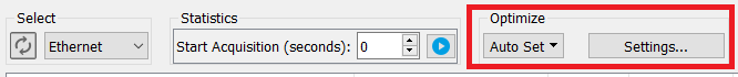
Auto set for interface or camera
The Auto Set algorithm allocates available bandwidth evenly between all cameras on the selected interface regardless of their maximum possible values. You can manually apply a different value with the slider or by entering the desired value and exclude these cameras from Auto Set by locking them.
If you want to prioritize a camera, adjust its bandwidth manually and then click the Lock icon.
Note
To prevent lost frames, the calculated bandwidth includes a safety margin.
Click Settings… to ajdust Auto Set. Note that the Settings only apply to the Auto Set procedure. Without clicking Auto Set, the Settings dialog has no effect.
Interface margin: The margin is substracted from the available interface bandwidth.
Camera margin: The required bandwidth is calculated and after that the camera safety margin is added to make sure that enough bandwidth is assigned.
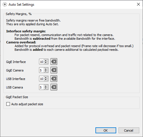
Settings to customize Auto Set
To access the Feature Tree, select the camera whose features you want to access.
To access all features, uncheck Show only bandwidth related features.
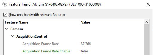
Features
Troubleshooting
Troubleshooting:
For best possible performance, the camera list is not updated automatically. To update the camera list, click Refresh camera tree. We recommend connecting all cameras before using Bandwidth Manager. If a camera is grayed out after refreshing, please wait a few seconds and then refresh again.
For the recommended hardware setup, read the User Guide for your camera.
Click Show Logging to expand the logging window.
Note that the Bandwidth Manager can provide a good starting point, but the best possible settings always depend on your use case.
Setting up your camera
Note
Available features and appearance GUI elements vary depending on camera interface and camera model.
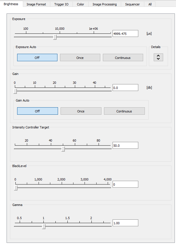
Brightness tab
The Brightness tab contains features for controlling exposure, gain, black level, and gamma.
Brightness tab
Exposure and Gain
To change the exposure time, either move the Exposure slider or enter a value and press the ENTER key. To enter exposure times in s, ms, and μs, click More.
Tip
If your camera does not reach the maximum frame rate, check if the exposure time is short enough. Example: If the exposure time is 100 ms, the camera cannot acquire more than approximately 10 fps.
To change the gain value, either move the Gain slider or enter a value and press the ENTER key. Your entry is automatically rounded up or down to the next possible value.
Using auto exposure and auto gain
The purpose of auto functions is to automatically compensate for changes of the lighting intensity. They use information from the camera’s current image and apply the optimized settings to the next image. Therefore, they can control values only if the camera is running. Large changes in scene lighting may require several frames for the algorithm to stabilize. The auto functions can be applied either once or continuously.
Tip
In most cases, you reach the best possible image quality by setting gain to the lowest possible value and increasing the exposure time as needed. The reason is that gain amplifies all image contents including noise.
If both auto features are used simultaneously, Exposure Auto has priority until ExposureAutoMax is reached. Then Gain Auto takes over priority.
See also
For a feature description, see the features reference document for your camera.
Image Format tab
On the Image Format tab, you can access:
Pixel format, binning, ReverseX/Y
ROI (Region Of Interest)
Autoregion ROI
Multi-ROI
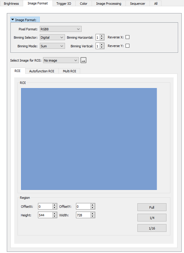
Image Format tab
See also
For a feature description, see the Features Reference document for your camera.
Pixel format
Select a pixel format of your choice. Note that Bayer pixel formats cannot be combined with white balance, color interpolation, and convolution mode. You can find information on pixel formats in the PFNC (Pixel Format Naming Convention): https://www.emva.org/wp-content/uploads/GenICam_PFNC_2_4.pdf.
Binning
Binning combines neighboring pixels into one pixel. This decreases resolution and increases light sensitivity. Depending on the camera model, binning may increase the frame rate. You can activate binning by selecting a value greater than 1 (binning = 1 does not affect the image).
Note
Alvium cameas: Binning cannot be used together with Multiple Regions.
ReverseX/Y
ReverseX/Y flips the image horizontally/vertically.
Note
Alvium cameas: ReverseX/Y cannot be used together with Multiple Regions.
Select an image
Optionally, you can select an image shown in the drag areas of the ROI tabs:
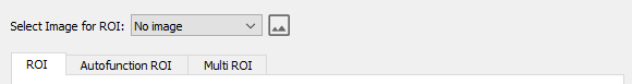
Select an image
If you use binning or change the ROI, do this before selecting an image.
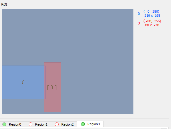
ROI
Selecting a ROI (Region Of Interest) enables working with a reduced image resolution to save bandwidth, achieve a higher frame rate (depending on the sensor), or crop the image according to your needs.
To select a ROI, either click in the blue ROI area and scale or move it with the mouse or enter values into the ROI fields. The buttons Full, 1/4, and 1/16 evoke a centered ROI of the full or partial image.
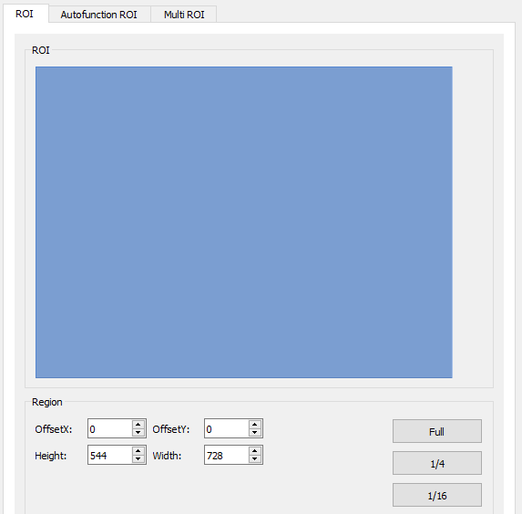
ROI
Autofunction ROI
Autofunction ROI means that the auto functions react to lighting changes only within the selected image section.
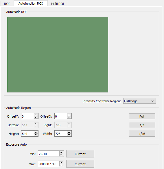
Autofunction ROI
Autofunction ROI is active as soon as auto exposure or auto gain are switched on. Therefore, click Full if you want to apply auto gain and auto exposure to the whole image.
To change Autofunction ROI, either click in the green ROI area and drag it or enter values.
The buttons Full, 1/4, and 1/16 evoke a centered ROI of the full or partial image.
Tip
Exposure Auto controls the minimum and maximum exposure time values in μs. If you want to reach the minimum frame rate, limit the exposure time accordingly.
Note
Alvium cameras: If Multiple Regions are used, Autofunction ROI uses Region0 only. Camera firmware issue: In Free mode, Autofunction ROI only works if Region0 is located above the other regions.
Multi ROI
Multi ROI provides access to Multiple Region Control camera features. Multiple region features can be used to assign different image settings to sections of an image, or to exclude irrelevant contents from the image output. In some cases, frame rates can be increased as well.
See also
For a description of the Multiple Region Control camera features, see: Alvium Features Reference, Multiple Regions of Interest for Goldeye
To work with multiple regions:
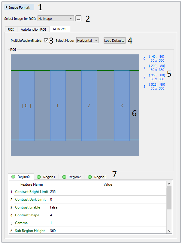
Multi ROI Horizontal Default
Multi ROI Troubleshooting:
Note that Alvium cameras automatically deactivate Regions with invalid values.
Some cameras have quite large minimum values for the Width (such as 264).
For an easy start with valid values, use Load Defaults, which is a convenience function of the Multi ROI tab.
To activate a Region with valid values, click the red outlined circle in the table header.
Invalid values and deactivated Regions are red
Note
Goldeye: The Multi ROI tab does not support the combination of binning/decimation with Multiple Regions.
Trigger IO tab
Note
Unsuitable connections may damage the camera or cause electrical shock. Before connecting external devices, read the instructions for your camera.
Trigger IO overview
Optionally, image acquisition can be started and stopped by a trigger signal from an external device or as a software command. Moreover, control signals can be transferred to external devices or additional cameras.
To trigger your cameras, you can use the presets as a start and modify them according to your use case. To configure trigger features such as Counters and Timers, open the Advanced Trigger dialog.
Note
If you change trigger features in the All tab, the Trigger IO tab preset doesn’t change to Custom.
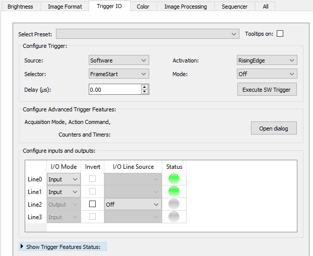
Trigger IO tab, click Open Dialog for advanced settings
In the I/O configuration table, a green status indicates true and a gray status indicates false.
The Advanced Trigger dialog provides access to all trigger-related features:
- I/O configuration: Set debouncing (Configure inputs and outputs table)
Debounce Mode Delay: LineDebounceDuration controls how long the signal level must be sustained for before it is accepted.
Debounce Mode Stall: LineDebounceDuration controls the intensity duration after the falling edge of the signal.
Action Commands (including PTP)
Software signal
Counter and Timer
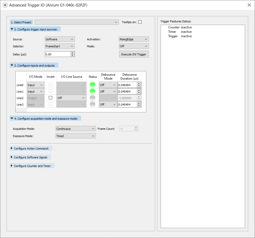
Advanced Trigger IO dialog
Presets
Turn Off All
Turns off all triggers and trigger sources, so that you can start image acquisition without using a trigger source. Other trigger settings like delay values keep their current settings.
Reset All
Resets all trigger features to default values. Other features such as white balance are not changed by this preset.
Custom
This preset becomes active when you apply changes to trigger features in the trigger IO tab.
Frame Trigger Software
Tip
The camera does not react immediately on a software trigger because a computer needs some time (latency) to process it. Since the CPU load varies all the time, the latency varies as well. If your application requires triggering with high precision, use a hardware device or, if your camera supports it, Trigger over Ethernet.
Trigger the camera by software:
Software trigger
FrameStart
RisingEdge
Continuous acquisition
Exposure mode: timed
To execute a software trigger, click Execute SW Trigger.
Frame Trigger IO Line0 Edge
Trigger the camera on rising edge:
FrameStart
RisingEdge
Line0
Continuous acquisition
Exposure mode: timed
Line0 (input)
Frame Trigger IO Line0 Level
Control the exposure time through an external device:
FrameStart
LevelHigh
Line0
Continuous acquisition
Exposure mode: trigger width
Line0 (input)
The camera exposes as long as the signal level from the trigger device is high.
Frame Trigger IO Line0 Bulk
Acquire an image series of n frames with a single trigger signal:
FrameStart
RisingEdge
Line0 (input)
MultiFrame, AcquisitionFrameCount: 10
Exposure mode: timed
PWM IO Line1 timer0 1khz 50%
Pulse Width Modulation with 1 kHz and 50% Duty Cycle:
Timer0, TimerDelay: 500, TimerDuration: 500
FallingEdge
Timer0Active
Line1 (output, source: Timer0Active)
Execute: TimerReset
Counter IO Line0
Count RisingEdge occurrences on Line0:
Counter0, CounterDuration: max
CounterEventActivation: RisingEdge
CounterEventSource: Line0, CounterResetSource: Off, CounterTriggerSource: Off
Line0 (input)
Execute: CounterReset
Trigger over Ethernet - Action Commands
Tip
If you use an Ethernet router, make sure all cameras are in the same subnet. Using a switch does not affect Action Commands.
See also
For detailed information, read the Action Commands application note.
Note
According to the GenICam standard, ActionDeviceKey is write-only. Reading the value from the camera is not possible (if the camera firmware complies to the standard).
Queue Size is read-only.
Using Action Commands requires configuring them first on the camera and then on the host PC.
To configure Action Commands on the camera:
In the Advanced Trigger IO dialog, select the desired values for the camera. If you want to use Scheduled Action Commands, select PTP Enable.
Adjust the other trigger parameters as required by your use case.
Click Freerun.
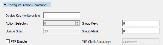
Action Commands - camera features
To configure Action Commands on the host PC:
While the camera window remains open, go to the main window and click Action Commands.
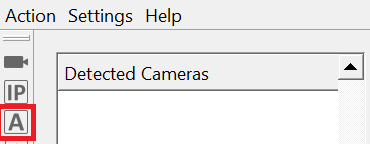
Trigger over Ethernet - Action commands
The Trigger over Ethernet - Action Commands window opens.
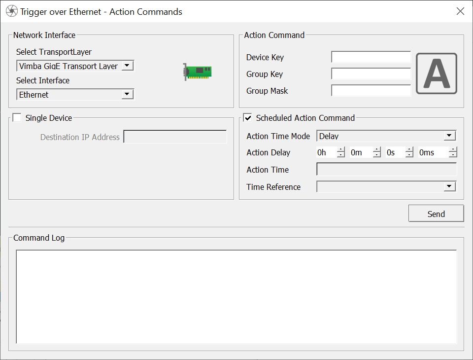
Trigger over Ethernet - Action commands window
Select the host adapter your cameras are connected to or select All interfaces.
Note
All Gigabit Ethernet adapters with a connected device are shown, even if the device does not support Action Commands.
Note
The Send Action Commands window does not reload when you plug in or out a camera. If you plug in GigE cameras while the Send Action Commands window is open, close the window, wait until the device is detected, an then reopen the window.
Select the desired interface. To trigger a single device, check Single Device and enter the device’s IP address.
Use the values for Device Key, Group Key, and Group Mask from the camera settings for the empty fields to configure them on the host PC.
To execute an Action Command, click Send. The Command log shows successfully sent Action Commands.
Note
Action Device Key must be set each time a camera was opened.
Scheduled Action commands:
Tip
Check if your camera firmware supports Scheduled Action commands.
To use Scheduled Action commands, activate PTP for all cameras that receive the command.
Delay: The Action Command is scheduled after a user defined time interval in ms. Minimum value: 20 ms.
Action Time: Copy the timestamp latch value (in ns) from the camera and add the desired time (in ns).
See also
For a feature description, see the GigE Features Reference. See also the technical manual or user guide of your GigE camera, chapter Camera interfaces for advanced settings.
Color tab
Note
The Color tab is available for color cameras only.
The Color tab contains features for controlling white balance, hue, and saturation as well as a color transformation matrix.
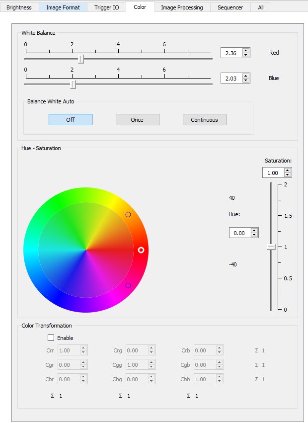
Color tab
Note
Hue, Saturation, and Color Transformation have no effect if you select any Bayer pixel format.
Auto white balance
Auto white balance automatically compensates for changes of the lighting source spectrum, for example, if artificial illumination is switched on and off additionally to daylight. Auto white balance uses information from the camera’s current image and applies the optimized settings to the next image. Therefore, it can control values only if the camera is running. Large changes in scene lighting may require several frames for the algorithm to stabilize. Auto white balance can be applied either once or continuously.
Hue and Saturation
In the color circle, hue is represented by the outer ring and saturation by the inner ring.
To change hue, click between the two small circles in the outer ring of the color circle (white circle: valid value, black circle: invalid value) or use the Hue box. To change saturation, click in the inner ring of the color circle or use the Saturation box or slider.
Color transformation matrix
The color transformation matrix enables you to adapt the color reproduction.
Color correction
Color correction compensates the overlap in the color channels. For example, a certain amount of blue light is “seen” not only by the blue pixels, but also by the red and green pixels. Depending on the spectrum of the light source and the sensor’s spectral response, different values are required to adjust the overlap and thus achieve the desired color reproduction.
In the color transformation matrix, Crr, Cgg, and Cbb represent the primary colors red (of the red pixel), green (of the green pixel), and blue (of the blue pixel).
For example, Crr represents red color of the red pixel. Increasing or decreasing Crr amplifies or attenuates red image components.
Values with two colors mean that the first color is mapped to the pixel of the second color. For example, Cgr means that green is mapped to the red pixel.
To better understand values affecting two colors, have a look at the Hue - Saturation circle.
For example, Cgr maps green light to the red color channel. Therefore, increasing Cgr amplifies green image components and shifts red image components towards green, resulting in a more orange red. Decreasing Cgr has the opposite effect: It attenuates green image components and shifts red image components towards magenta (the distance from red to green is larger).
Tip
For natural color reproduction (depending on the sensor’s capabilities), make sure all row sums are 1. Values that deviate from 1 may result in tinted images.
Tip
In machine vision, color correction is often used to emphasize a color of interest, to enhance the difference between two similar colors, or to reduce image complexity.
To reset the matrix to its default values, click Reset.
Image Processing tab
Default functionalities
Note
The Image Processing tab is available only for cameras with compatible ImageProcessingControl features.
The Image Processing tab contains features for contrast stretching (ContrastControl), color interpolation, and Convolution Mode.
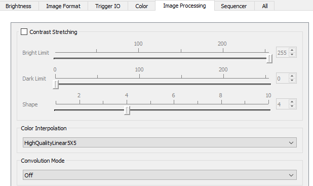
Image Processing tab
Custom Convolution
If you select Custom Convolution as Convolution Mode, a matrix opens and you can enter the desired values.
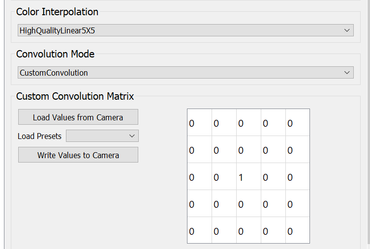
Custom Convolution
Tip
If you want to use different custom convolution values, we recommend saving them together with the the other camera settings as an XML file.
If the value deviates from the preset and is present in the camera (for example, in the user set or because have changed it in the All tab), click Load Values from Camera to take over the values in the matrix.
To apply new values to the camera, click Write Values to Camera.
Note
The All tab reads and writes the custom convolution values directly. On the Image Processing tab, make sure to use Load Values from/to Camera.
Sequencer tab
Sequencer overview
The Sequencer tab is available for Alvium cameras with Sequencer features and firmware v13 or higher.
See also
For a detailed description of the complex Sequencer functionality, see our application note
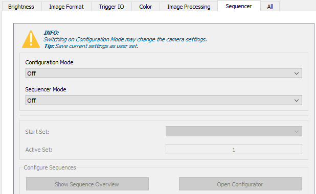
Sequencer tab
The Sequence Overview shows sets and paths that are contained in a sequence. It is available in the tab and in the Sequence Configurator. The Active Set is bold.
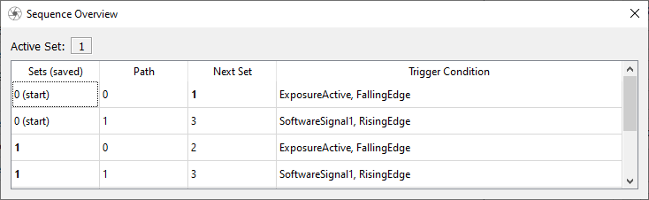
Sequence overview
Sequence Configurator
If Configuration Mode is on, you can use the Sequence Configurator.
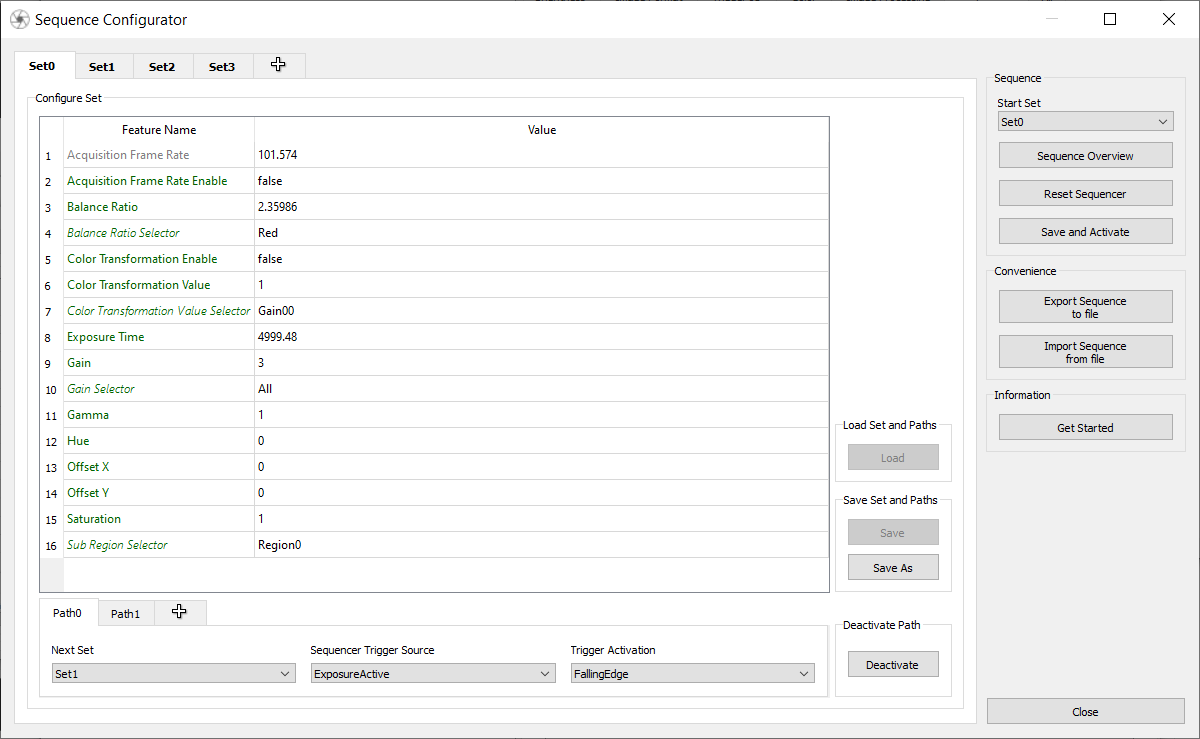
Sequence Configurator
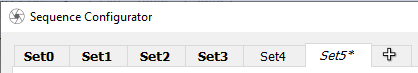
Sets in a sequence, not in a sequence, not saved
Notes on configuring sets:
Sets that are saved in the camera and contained in a sequence are shown in bold.
Unsaved sets have an asterisk*.
In the Next Set drop-down list, sets that don’t yet exist in the camera are shown in italics.
Changing values in the Sequence Configurator doesn’t automatically save them to the camera.
If you leave a set, save it to the camera if you want to keep its data.
Once a set is stored in the camera, it can be deleted only if you delete the Sequencer configuration. This is camera behavior.
By default, Set0 is shown as start set and Set1 is shown as active set - even if the sets don’t exist in the camera.
To get the current active set with high precision, use Chunk.
Behavior of paths:
You can configure a sequence with just one path. Using multiple paths is optional.
A sequence may contain multiple paths.
If multiple paths are used, then the path with the highest number has the highest priority.
Sequencer features: - In contrast to the All tab, the Sequence Configurator only
shows features with Sequencer Feature Enable value True.
For your convenience, Feature selectors such as Balance Ratio Selector are shown in the Sequence Configurator in italics. Note that the feature selectors are not available in the SequencerControl category. Always save non-SequencerControl features in a user set and call this user set before configurating and activating a sequence.
Reset Sequencer:
The reset deletes all sets in the camera.
You can always export existing sequences to a JSON file.
Using JSON files for sequences
You can always export sequences from the camera to a JSON file. Sometimes it is quick and easy to configure the first set, path, and next set in the Vimba X Viewer and to continue with the configuration directly in the JSON file.
Note
If you import a JSON file, it is directly imported to the camera. Existing sequences are overwritten.
Note
Note that only currently writeable features are exported to JSON.
As a starting point for your sequences, you can use the Alvium Example Sequence file: Sequencer_Presets.json. To access this file, click Import Sequence from file. It uses a workaround for an issue described in the camera release notes for firmware 13.
If the JSON file contains features that the camera doesn’t support, they are not loaded there is and no error message.
If the JSON file has an invalid structure or doesn’t contain any sets, an error message is displayed.