Vimba Viewer Guide
Overview
This document guides you through the basic camera setup with the Vimba Viewer. You will learn how to select, control, and save settings such as image size, exposure time, and color display.
See also
For information on camera and driver installation and a detailed feature description, download the corresponding documents for your camera.
Note
Depending on the camera model, different features are available. The screenshots and examples in this document are generic.
Prerequisites
This manual assumes you have already installed and configured the host adapter card or frame grabber according to the instructions for your camera.
Quick start
To use Vimba Viewer:
Connect the camera to the host.
Start Vimba Viewer.
Click the camera you want to open.
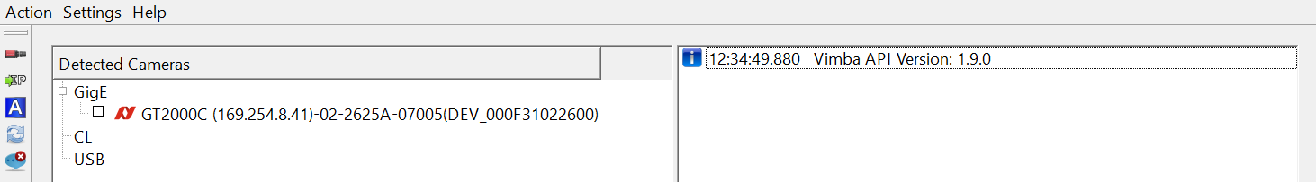
Open camera
The main window opens.
To start image acquisition, click Freerun.
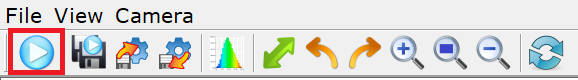
Start continuous image acquisition (freerun)
GigE/CL cameras
If Freerun is grayed out:
GigE: Click ForceIP. If Freerun is stil grayed out, correct the GigE settings (you can find instructions in the camera manual).
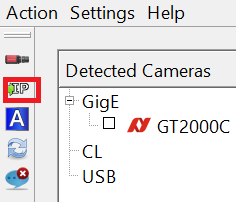
Force IP
Camera Link (Windows only): You can use Vimba Viewer to configure Goldeye CL cameras and to set features. To acquire images, use the software provided by the frame grabber manufacturer.
See also
For smooth operation and best performance, follow the instructions for your camera.
Vimba Viewer tabs concept
To select and configure settings, Vimba Viewer provides tabs with basic grouped camera features and the All tab, which contains a list of both the basic features and advanced features.

Viewer tabs
To quickly set up your camera, we recommend going through the tabs from left to right (except for Goldeye CL). The basic features can be adjusted either on the All tab or on the other tabs, whereas advanced features are available on the All tab only.
Note
The Color tab is available for color cameras only.
Finding features in the All tab
To quickly find features from the other tabs in the All tab, enter their first letters in the Search field.
The All tab provides tooltips and an optional feature description window. The description also lists which other features are affected by the selected feature.
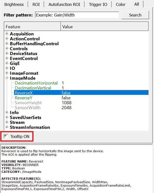
Tooltips
Starting and stopping image acquisition
To start and stop image acquisition, click Freerun.
Freerun
Loading and saving settings
Additionally to the user sets stored inside the camera, you can save the feature values as an XML file to your host PC. You can load this camera settings XML file to a camera or use the XML file with the Vimba APIs. To load or save a settings file, click Load and Save.
Load and save settings
Using saved settings files with Vimba API
To use a saved settings file with Vimba API:
Set up your camera with Vimba Viewer.
Save the settings.
Load the settings with the API (see the example and the API manuals).
Saving images
Saving one image
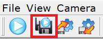
In the File menu, click Save Image As…
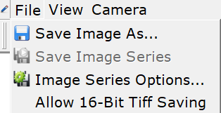
File menu
The Save Image window opens and you can save one image.
You can save the current image while the camera is running or you can save the current image displayed in Vimba Viewer while the camera is stopped.
Saving an image series
If the camera is running, stop image acquisition.
In the File menu shown above, click Image Series Options….
The Saving Options window opens. In the dialog, make sure the Number Of Images is > 0, select the other options, and click OK.
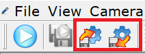
Now Save Image Series is active. Clicking it triggers acquiring and saving the defined number of images. You can also use the icon:
Save image series
If the icon is grayed out, make sure that image acquisition is stopped and the selected number of images is > 0.
Saving 16-bit images
By default, Vimba Viewer saves 8-bit images, regardless of the selected pixel format or file format. Optionally, all images with mono or Bayer pixel formats > 8-bit per channel (e.g., Mono10, BayerRG12Packed, Mono14) can be saved as 16-bit TIFF. To enable this option, select Allow 16-Bit TIFF Saving.
Save 16-Bit Tiff
Tip
The option for saving 16-bit image files is not optimized for performance. Therefore, it is deselected by default when a camera is opened. We recommend selecting it on demand.
16-bit image files are saved if these conditions are true:
Allow 16-Bit TIFF Saving is checked.
TIFF or TIF is the selected file format for image (series) saving.
The camera’s current pixel format is a mono or Bayer format > 8 bits per channel.
Supported pixel formats:
Mono10, Mono10p
Mono12, Mono12p, Mono12Packed
Mono14, Mono16
BayerGR10, BayerRG10, BayerGB10, BayerBG10, BayerGR10p, BayerRG10p, BayerGB10p, BayerBG10p
BayerGR12, BayerRG12, BayerGB12, BayerBG12, BayerGR12Packed, BayerRG12Packed, BayerGB12Packed, BayerBG12Packed, BayerGR12p, BayerRG12p, BayerGB12p, BayerBG12p
BayerGR16, BayerRG16, BayerGB16, BayerBG16
Options
Go to View → Options to:
Display every completed frame (increases CPU load, not recommended for most use cases)
Change the number of used frame buffers
Enable or disable Alloc and Announce, which may optimize buffer allocation (depending on your use case).
Setting up your camera
Note
Available features and appearance GUI elements vary depending on camera interface and camera model.
Brightness tab
The Brightness tab contains features for controlling exposure, gain, black level, and gamma.
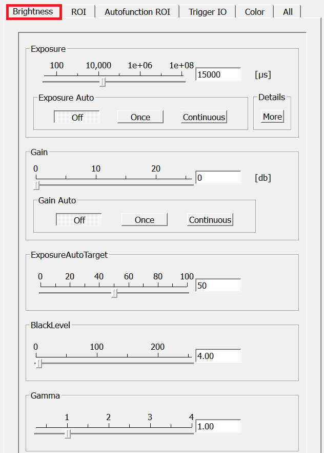
Brightness tab
Exposure and Gain
To change the exposure time, either move the Exposure slider or enter a value and press the ENTER key. To enter exposure times in s, ms, and μs, click More.
Tip
If your camera does not reach the maximum frame rate, check if the exposure time is short enough. Example: If the exposure time is 100 ms, the camera cannot acquire more than approximately 10 fps.
To change the gain value, either move the Gain slider or enter a value and press the ENTER key. Your entry is automatically rounded up or down to the next possible value.
Using auto exposure and auto gain
The purpose of auto functions is to automatically compensate for changes of the lighting intensity. They use information from the camera’s current image and apply the optimized settings to the next image. Therefore, they can control values only if the camera is running. Large changes in scene lighting may require several frames for the algorithm to stabilize. The auto functions can be applied either once or continuously.
Tip
In most cases, you reach the best possible image quality by setting gain to the lowest possible value and increasing the exposure time as needed. The reason is that gain amplifies all image contents including noise.
If both auto features are used simultaneously, Exposure Auto has priority until ExposureAutoMax is reached. Then Gain Auto takes over priority.
See also
For a feature description, see the features reference document for your camera.
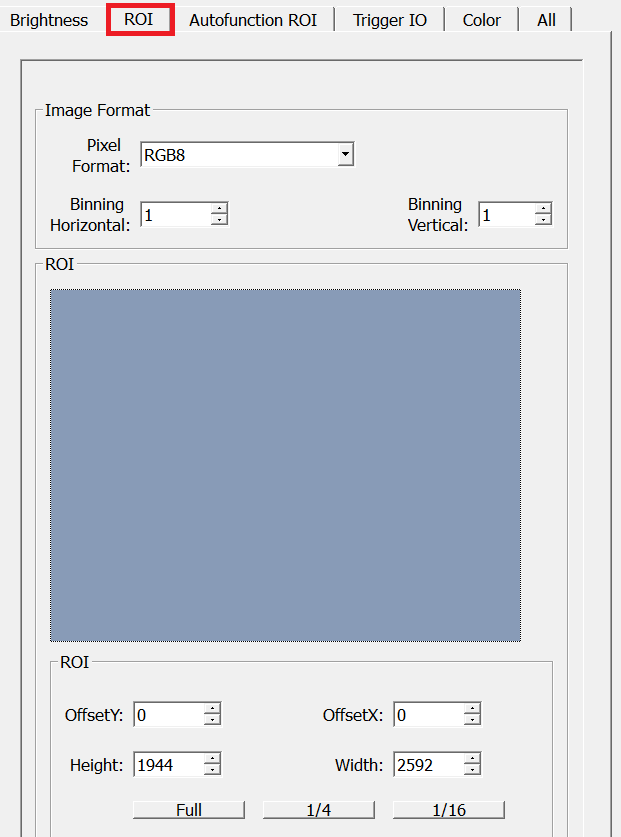
ROI tab
Selecting an ROI/AOI (region of interest/area of interest) enables working with a reduced image resolution to save bandwidth, achieve a higher frame rate (depending on the sensor), or crop the image according to your needs. Moreover, some cameras support binning.
ROI/AOI tab
Setting up ROI and binning
To set up the basic image format:
Select a pixel format. Optionally (and if your camera supports it), activate binning by selecting a value greater than 1 (binning = 1 does not affect the image). Binning combines neighboring pixels into one pixel. This decreases resolution and increases light sensitivity. Depending on the camera model, binning may increase the frame rate.
Select an ROI. To do this, either click in the blue ROI area and scale or move it with the mouse or enter values into the ROI fields. The buttons Full, 1/4, and 1/16 evoke a centered ROI of the full or partial image.
See also
For a feature description, see the features reference document for your camera.
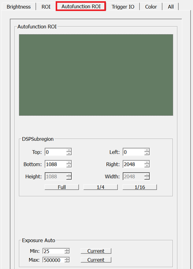
Autofunction ROI tab
Autofunction ROI means that the auto functions react to lighting changes only within the selected image section.
Tip
If your camera has the Intensity Controller Region feature, go to the All tab and make sure AutoModeRegion1 is switched on.
Autofunction ROI tab
With GigE cameras, Autofunction ROI (the DSPSubregion feature) is active as soon as auto exposure or auto gain are switched on. You cannot switch off DSPSubregion. Therefore, click Full if you want to apply auto gain and auto exposure to the whole image.
To change Autofunction ROI, either click in the green ROI area and drag it or enter values.
The buttons Full, 1/4, and 1/16 evoke a centered ROI of the full or partial image.
Tip
Exposure Auto controls the minimum and maximum exposure time values in μs. If you want to reach the minimum frame rate, limit the exposure time accordingly.
Trigger IO tab
Note
Unsuitable connections may damage the camera or cause electrical shock. Before connecting external devices, read the instructions for your camera.
Optionally, image acquisition can be started and stopped by a trigger signal from an external device or as a software command. Moreover, control signals can be transferred to external devices or additional cameras.
Trigger tab
Tip
Allied Vision cameras offer numerous options for triggering and I/O configuration. The Quick Settings cover typical machine vision scenarios. You can use them as a start and modify all features according to your needs.
See also
Before triggering with external devices, read the instructions for your camera.
Scenario A: Master/subordinate mode
If you want one camera to serve as master and a second camera as subordinate, connect the trigger device with the master camera’s input and connect the subordinate camera with the master camera’s output (for I/O pin assignments, see the user documentation of your camera).
To configure master/subordinate functionality, open both cameras with Vimba Viewer:
Master camera:
Click the Edge button.
Select Source: Select the chosen input, for example, Line 1
In the Output section, go to SyncOut and select Exposing.
Click Freerun.
Subordinate camera:
Click Edge. Make sure that Source is switched to your selected input.
Click Freerun.
Now both cameras start acquiring images when the trigger signal edge is falling.
Scenario B: Controlling exposure externally
To control the exposure time with an external device, connect the trigger device with the master camera’s input:
Click Level.
Click Freerun.
Now the camera exposes as long as the signal level from the trigger device is high or low (select Activ.: LevelHigh or LevelLow).
Scenario C: Acquiring an image series
To acquire n frames with a single trigger signal:
Click Click Bulk.
Click Freerun.
Now the camera acquires an image series when it receives a trigger signal. To select the desired number of frames, enter the number in the FrameCount box. By default, the frames triggered with Bulk mode are acquired with the maximum possible frame rate. To acquire the image series with a frame rate of your choice:
Go to the All tab.
Select AcquisitionFrameRateAbs.
Enter the desired frame rate.
Scenario D: Software trigger
Tip
The camera does not react immediately on a software trigger because a computer needs some time (latency) to process it. Since the CPU load varies all the time, the latency varies as well. If your application requires triggering with high precision, use a hardware device.
To trigger the camera by clicking SW Trigger:
Select Source: Software. (If Software is unavailable, click Edge.)
Checkmark Mode: On/Off.
Click Freerun.
Now the camera starts acquiring images when you click SW Trigger.
Scenario E: Trigger over Ethernet - Action Commands
Note
Action Commands are supported by selected Allied Vision GigE camera models with the latest firmware.
Tip
If you use an Ethernet router, make sure all cameras are in the same subnet. Using a switch does not affect Action Commands.
See also
For detailed information, read the Action Commands application note.
Using Action Commands requires configuring them first on the camera and then on the host PC.
To configure Action Commands on the camera:
On the Trigger IO tab, select Source: Action0 or Action1 and Mode: On.
Adjust the other trigger parameters as required by your use case.
On the All tab, open ActionControl and enter your desired values.
Click Freerun.
To configure Action Commands on the host PC:
While the main window remains open, go to the Camera Selector window and click Action Commands.
Trigger over Ethernet - Action commands
The Trigger over Ethernet - Action Commands window opens.
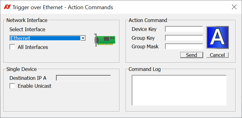
Trigger over Ethernet - Action commands window
Select the host adapter your cameras are connected to or select All interfaces.
Note
All Gigabit Ethernet adapters with a connected device are shown, even if the device does not support Action Commands.
Note
The Send Action Commands window does not reload when you plug in or out a camera. If you plug in GigE cameras while the Send Action Commands window is open, close the window, wait until the device is detected, an then reopen the window.
Select the desired interface. To trigger a single device, check Enable Unicast and enter the device’s IP address.
Copy the values for Device Key, Group Key, and Group Mask from the camera settings into the empty fields to configure them on the host PC.
To execute an Action Command, click Send. The Command log shows successfully sent Action Commands.
Note
Action Device Key must be set each time a camera was opened.
Advanced trigger and I/O settings
In addition to the Quick Settings, the Trigger IO tab provides advanced settings. More information is provided in the following documents:
See also
For a feature description, see the GigE Features Reference. See also the technical manual or user guide of your GigE camera, chapter Camera interfaces for advanced settings.
See also
For more information on triggering, read our application notes.
Color tab
Note
The Color tab is available for color cameras only.
The Color tab contains features for controlling white balance, hue, and saturation as well as a color transformation matrix.
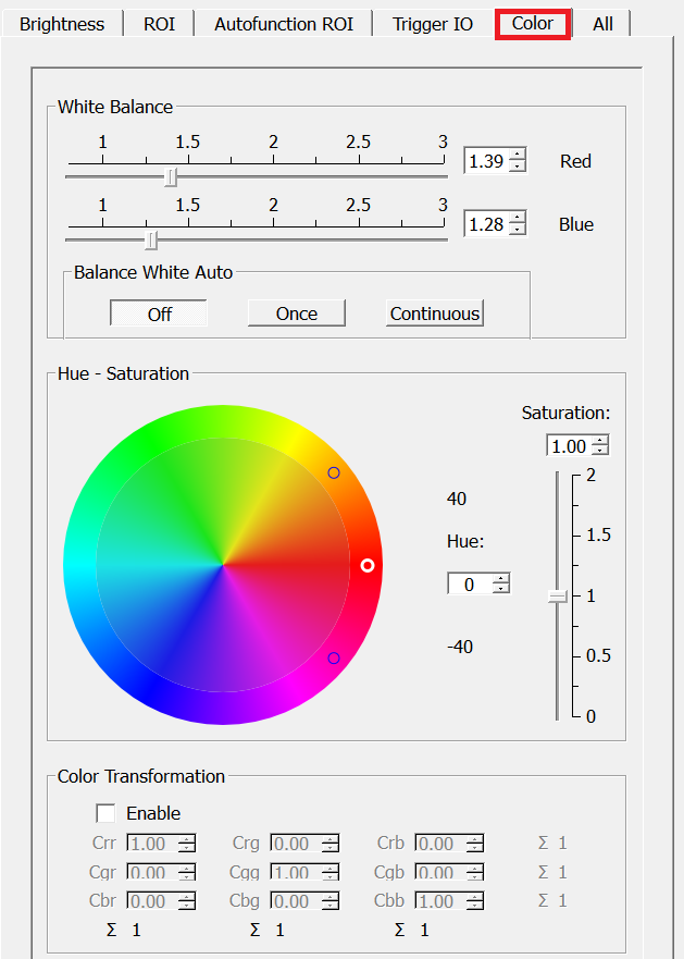
Color tab
Note
Hue, Saturation, and Color Transformation have no effect if you select any Bayer pixel format.
Auto white balance
Auto white balance automatically compensates for changes of the lighting source spectrum, for example, if artificial illumination is switched on and off additionally to daylight. Auto white balance uses information from the camera’s current image and applies the optimized settings to the next image. Therefore, it can control values only if the camera is running. Large changes in scene lighting may require several frames for the algorithm to stabilize. Auto white balance can be applied either once or continuously.
Hue and Saturation
In the color circle, hue is represented by the outer ring and saturation by the inner ring.
To change hue, click between the two small circles in the outer ring of the color circle (white circle: valid value, black circle: invalid value) or use the Hue box. To change saturation, click in the inner ring of the color circle or use the Saturation box or slider.
Color transformation matrix
The color transformation matrix enables you to adapt the color reproduction.
Color correction
Color correction compensates the overlap in the color channels. For example, a certain amount of blue light is “seen” not only by the blue pixels, but also by the red and green pixels. Depending on the spectrum of the light source and the sensor’s spectral response, different values are required to adjust the overlap and thus achieve the desired color reproduction.
In the color transformation matrix, Crr, Cgg, and Cbb represent the primary colors red (of the red pixel), green (of the green pixel), and blue (of the blue pixel).
For example, Crr represents red color of the red pixel. Increasing or decreasing Crr amplifies or attenuates red image components.
Values with two colors mean that the first color is mapped to the pixel of the second color. For example, Cgr means that green is mapped to the red pixel.
To better understand values affecting two colors, have a look at the Hue - Saturation circle.
For example, Cgr maps green light to the red color channel. Therefore, increasing Cgr amplifies green image components and shifts red image components towards green, resulting in a more orange red. Decreasing Cgr has the opposite effect: It attenuates green image components and shifts red image components towards magenta (the distance from red to green is larger).
Tip
For natural color reproduction (depending on the sensor’s capabilities), make sure all row sums are 1. Values that deviate from 1 may result in tinted images.
Tip
In machine vision, color correction is often used to emphasize a color of interest, to enhance the difference between two similar colors, or to reduce image complexity.
To reset the matrix to its default values, click Reset.